I have always loved sailing, something about being able to be so hands on while enjoying the sunshine and the open water is just entrancing and it all started the first time I went sailing while in Boy Scouts, probably around the age of 13. Fast forward a number of years and I had finally made one of the larger mistakes in my life and purchased a modest first sailboat, a 1971 MacGregor 22’ sailboat, just an absolute dump that floated. But it was my dump, and like many of my DIY projects it came longer before this blog existed and was a real learning experience. After working on it for a few months, mainly just redoing the interior and replacing the rigging, we were ready to take her out. And she was a lot of fun, we broke her a few times and fixed her up but that was exactly her purpose. One extremely windy October day in 2016, a willow tree decided to leave its comfy hole in the ground and take a nap right on top of my good old sailboat.
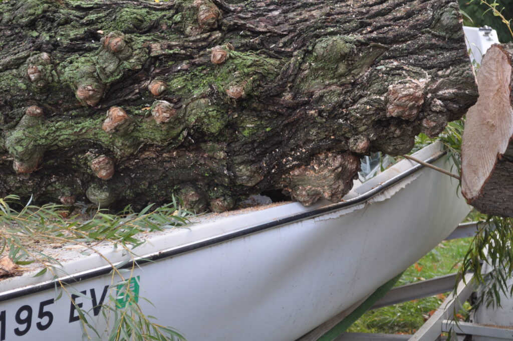
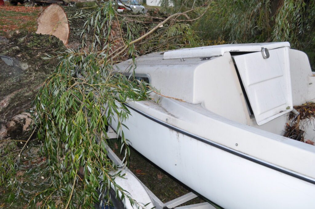
Needless to say, it is a good thing we had insurance covering it making it not a total loss, and a big plus was that the insurance company was going to let me figure out how to get rid of a huge fiberglass sailboat! Enter the best summer bonfire of 2017, and now all that was left was the trailer. At first I did want to just get rid of the thing all together, I mean it was only slightly bent and had a straight axle and tongue so it was easily convertible into a hauling trailer for whatever purpose. I got no offers on the trusty Craigslist or Facebook Marketplace so eventually I decided to just cut it up into decent lengths of repurpose-able C-channel steel.
The sawmill was not the first idea I had for my newly salvaged material, I thought about a DIY stump grinder and even making a pumpkin trebuchet because who doesn’t want to hurtle a pumpkin a few hundred yards into a vineyard. After careful consideration of necessity and legality concerns I decided that a sawmill would be a worthy candidate.
A quick search on Google assured me of two things really:
1) This was an entirely feasible project to undertake.
2) While a limited number of people have done it, only a select few of those people have provided DIY articles.
There was really not too much thought put into where I wanted to start building, I just assumed that I wanted to cut a log of diameter X and and very in length. Main design points were I wanted the carriage to move and the track to be ‘fixed’ but both were able to be separated and transported to the trees to-be-felled. So lets get started on this as-we-go engineering.

MATERIALS
Aside from a plethora of salvaged materials, namely steel, here is a list of items that comes to my mind for any DIY preparing to take on this task. These are the basic materials but are not limited to….
- Hack Saw
- Combination Wrenches
- Hex Wrenches
- BF Hammer
- Grinder
- Welder (stick/MIG/TIG/OxyAcet are all fine)
- Tape Measure
- Square
- Drill and Drill Bits
- Various Nuts and bolts
- Winch, cable or belt if fine need pulleys to match
- 8″ Thread Stock
- Various Steel Supply
- Wheels (dummy tire or other)
- Saw Mill Blade of proper size (see Step 1)
- Bearings, lots of them
- At minimum 3 Pulleys or calculated size (see Step 5)
- Band Aids and other first-aid supplies
- A nice glass of whiskey and a cigar (always drink responsibly)
- Some smooth jazz playing in the background as you rain down thunder with your clearly unnecessarily sized hammer is making fine adjustments
STEP 0: SIZE UP YOUR WOOD
Very simple, not really a step because what lead you to find this page is probably that you want a board of a certain size for the not so modest price. You need to decide within a reasonable amount what the largest width of tree you want to be cutting is. If there are other size considerations that come into play (ie where you intend to do the milling, inside?) take note of those and make sure your rough design measurements work out with it. I intend to take this machine to wherever a tree may call my wondering spirit, so I don’t have those kinds of constraints.
STEP 1: BLADE ORIGIN
This may seem like an odd place to be starting, but I honestly don’t think there would be a better choice. Blade length will determine what style/size of wheel you want which will also determine the size of the throat of the sawmill and therefore what the largest tree you can cut will be.
I might also mention that choosing a blade size does not mean buying one, however if you choose an odd size, you’d best buy at least a couple to make sure you have some before they stop making them(more on this later). In choosing the blade I had some other limitations as well since I was only using what I had immediately available to build this, buying anything other than some hardware or welding supplies was really what I wanted to avoid for this project, aside from the blade. For my saw I initially ended up going with a 200” x 1.5” x 10º Wood Mizer Blade, I will go more into detail about the math I used to select the blade length in the next few steps.
STEP 2: WHAT IN THE WHEEL!
For selecting a wheel you need to consider everything in the first step, as well as the costs. You can buy wheel kits online that race from like $175 on but thats not the point of this project so I used what any local junk yard would be glad to give away (see what I did there) a set of donut tires. My choice for this was because I had the grease-able hubs off the axle of the trailer so I didn’t need to buy any surface mount bearings or spindles, etc. Plus as long as these tires are generally the same size, the tensioner will take out the difference and a little slant (while unappealing) will end up being fine in the boards so long as it is straight and parallel.
Now that I had my wheels diameter and I knew what size tree I wanted to be able to attempt to cut, I could do a little math to figure out some other numbers. We know the diameter of or wheels, whatever that may be in your instance for me it is about 22.5 inches. To get the total circumference of the wheel we use the equation 2πr, now we don’t need to double this for both wheels because the blade only rides on half the circumference of each wheel. Since We know each wheel grips that much blade (we will represent this by G) and we know how wide of a board we want to be able to slice (represented by T) we can solve for L. Once we have L we can double it (for top and bottom distance) and add G. This picture below represents what I am trying to explain, for more visual people.
It should be noted that T is 5-7 inches longer/wider than the max width of a tree, to account for frame positioning and blade guides.
You can enter you values in here and see what you get but it only Neds to be close and preferably less for tension, my example is below.
T – maximum log width + clearance
G -blade taken up by wheel circumference
r – radius of wheel
W – blade length total
W = 2πr + 2T
ex. ~200” = (2*π*22.5”) + (2*29.25”)
STEP 3: FRAME! FRAME! FRAME!
So now we get to a bit more hands on dirty work, designing and building the frame. This is a bit of an interesting area because you really have so many choices to go with, as long as it ends up meeting your width requirement, doesn’t bend and break, and can handle the torque from the cut. A lot/most/maybe all the bandsaws I have seen this far are kind of the same way, a square tube length of ~16 inches in length riding up and down another square tube that fits just inside with corner lock bolts to prevent slipping when the proper height is reached. This really is a good way to do it, however I had a very limited supply of square tubing and according to my main rule of this build, I was not going to be buying any either, considering square tubing is generally quite pricy even for relatively short lengths, pricy compared to already have salvaged. I decided to just get started cutting, I had torches to use but lucky me forgot to grab acetylene for them so most of my cuts are actually done the good old fashioned way, as I am renowned for my ability to break and bend reciprocating saw blades. A you may have noticed from my photos, these pipes for arms I have helped along the way (joke).
The design for my frame was pretty basic, an upside down ‘U’ shape with a ’T’ on either end of the U sticking what would be straight out of the page (see photos). I also made a pint to not weld as much as possible, the bolt together design introduced a lot of issues with rigidity that needed attention, but ultimately allow for ease of repair in the field. You do not need to go this route, if you want t weld everything together because its faster, sturdier, and works better for you then by all means do it since you’ll be saving yourself from using a bunch of good hardware laying around that could be use for other projects anyways!
Here you can see how my frame and carriage will site together and a mock up of how I wanted the roller slides to end up (more on these later). The outer edge of the frames C channel goes all the way to the inner edge of the wheels, not that they could not be further out or closer in, I just liked the idea of having the wheels be in line that way. there really is a lot of play in the ‘design’. You Can see how the carriage has the flat edge of my C channel riding against the flat edge of the frame C channel, if your design is anything like mine in material this is VERY important to prevent seriously unnecessary wear.
I chose to use a roller guide on at least one of the moving planes because I have used a sawmill before and one thing I experienced during use was that the square tubs bind against each other and it becomes incredibly annoying to have to raise the carriage after you just tried to lower it two inches. this should prevent that while provide stability. Again, not required but I thought of it as a bit of an upgrade.
In the picture above you can see what I meant in my description that the upside down U shape has two T tops attached what would be sticking out of the page. The pipe clamp is just to stop the Fram from spreading out, this issue was expected and dealt with with a later adaptation.
This short clip shows how I used the hand winch from the boat and a cable from the rigging to create the up down action. You can see that it is a bit ‘jumpy’ this is because there are just C clamps holding the two parks of the carriage together for now, but you also may notice that only one of the roller guides is spinning. Not only is this fine because I expected a bit a of play that would allow this, but at this time the carriage is having a hard time sitting square due to the fact that the bottom is only being held in position by a oddly placed pipe clamp, a temporary fix.
This photo shows how I bolted the hubs to the carriage, the hubs have solid round piece of steel stick straight out of the back (center) and a square tube welded to that, I took advantage of the square tube and left about 4″ on it to bolt it to the edge of the C channel. Instead of fighting with nuts and wrenches inside of the square tubing, and not wanting to use a 4″ bolt straight through it, I made these little blocks (shown below) to bolt into and keep each other tight.
One of the downfalls of using the dummy tires as the blade wheels is the weight factor. I mentioned before that the frame needs to be able to withstand the torquing action of cutting a log, what I did not originally think of as being an issue is the lopsided weight of the carriage being so front heavy. This would surely cause the blade to just dive nearly straight down into the board, ruining a lot of potentially good cuts. However this was corrected what must of been subconsciously, by the weight of the engine.
STEP 4: SHE NEEDS MORE POWER!
There are two ways to give this machine heart, well I guess three if you want to use a water wheel but you are on your own with that one. The most common application of power for a portable sawmill is an engine but I have seen some that use an electric motor, and there are advantages/disadvantages to both. While an electric motor of the proper specifications will provide very consistent power immediately to the blade you loose a lot of versatility in the portable idea. Yeah you can take it with you places, but you either need a generator or an outlet in order to run it. Another big advantage to me is the quietness of the electric motor idea compared to an engine. That being said, when it comes right down to it I think that a gas engine will always win in a power/weight within a certain price range, the engine was an item I had to purchase for this project, but I did so buy buying a broken power washer off of Craigslist and salvaging a lot of parts from that including the engine. Now some people have use 7-8HP engines for their sawmills, but unless you have one that size on had it seems quite foolish as at that power you are really limiting your ability to cut boards over some width. The engine I ended up going with is a 10HP and that is really the minimum I would recommend, ideally 12HP or more because is there really a such thing as too much power?
STEP 5: PULLEY PALOOZA
Now I only had a couple of small sections of square tubing sitting around, but it ended up being just enough to give me the distance needed to counteract the weight of the wheels and provide clearance for the pulley system. Make sure there is enough clearance! You can put one belt the entire distance if you mount the engine the right way, but you need to make sure your feet per minute end up correct (explained in next step) so I needed to have a couple more pulleys, allowing me to hide the belt away from any hazardous boards waiting to tear it up. If you look closely you will notice that there are two pieces of angle iron on the outer edge of the frame, bolted to the carriage. These are the outer guides and also have the locking bolts on them to prevent the carriage from shifting position during a cut. There is also a slight difference in the distance between the left/right wheels and respective frame edges. The left one is closer to the frame because the slot cut for tensioning the blade allows the wheel to go in that far. The right wheel shows the total space space and is fixed in location (aside from tracking adjustment) because it is the driven wheel. The space between the right frame/wheel will eventually be taken up by the ‘transmission and clutch’.
One of my ‘genius’ ideas was to use a rotor as the wheel pulley, and put the dummy tire on inside out so that the belt can fit around. This actually worked surprisingly well and doesn’t shred belts like I thought it would, if you have an engine lathe handy and can turn down the sharp corners of the rotor to stop the wear even more, fantastic but if not it will still work fine, you may just have to sacrifice an old belt for the initial wearing like I did. I actually didn’t buy any belts/pulleys/bearings, everything was salvaged from all kinds of thins, I just gathered part after part for a long time and suddenly realized I had all the pars to do it, just needed frame material. Boy did I get my wish!
It is extremely important to make sure you are at least in the ballpark of the power feet per minute for the blade. Most manufacturers put that between 5000 ft/min – 5500 ft/min but it may vary so check with your blade manufacturer, being in the ballpark of a 250ft/min variance is perfect, but you have to do the math on this. There are excellent online calculators out there that help you do this by allowing you to put in the two pulley sizes, the distance between centers, and the rpm of one or the other. It will calculate the rpm and the ft/min for you, I have an example of the calculator below that I used.
Its okay to go through different renditions of design as well, I would just recommend not doing something so catastrophic to your machine that you have to make another major piece all over again. I did two different styes of the transmission, my first was just using old oil-able brass bushings in brackets and a shaft from inside of an old furnace blower I used to use as a home construction exhaust fan. Parts can literally be everywhere, just look and get them. My final design was a pipe that has bearings pressed into the end, sitting in a cradle held down with an exhaust clamp. it is an extremely effective design and allows me to pull one small part to replace the bearings (which are a very common size) if needed. The original idea of mine is shown below.
STEP 6: AND SQUEEEZE
I wil admit I kind of cheated on the clutch system, but not really. I mean its all about salvaging parts for later projects right? Well I got my belt tensioner from a vintage rototiller destined for the scrap yard. Saved just in time too because it was being loaded on the trailer as I was trying to pull it off!
Now I didn’t totally cheat because I did have to fabricate a mounting system for it, and a cable system as well.
Before anything is said, that pipe was just a scrap piece it was not the final part used! I actually took a smaller piece of pipe and bored it on either end for a bearing to sit, and I have proof see! The lather was not top of the line, but it got the job done within .003″ on each bore, and that was using my Lufkin inside mics.
Now once it was all fit in there I greased these bearings up the same way I loaded the transmissions bearing housing with grease. I am hoping to not have to replace these old skateboard bearings for years and years to come.
Originally the bottom of the belt was going to ride over the top of the clutch pulley (as photoed) but this idea was vetoed due to the belt not being given enough slack when the clutch was disengaged, so the driven wheel kept spinning. I ended up putting the belts the opposite way, which had the same effect but allowed much more forgiveness in the belt tension when the system was relaxed.
Yes the pulley has a chip, which is why it ended up with me getting repurposed in the first place!. Aside from it effecting the balance of the pulley slightly, It has yet to cause any other issues.
Once it was mounted a cable was attached to a freely rotating pin on the bottom (see photos) and ran over to a simple lawnmower style clutch engagement system. The cable used was actually salvaged from a lawnmower as well, thumb up for reduce, reuse, recycle!
STEP 7: BLADE TRACKING AND MORE
Something that as to be decided is ho you want to cause the blade to track. Despite common belief, a bandsaw style sawmill blade does not sit straight in line (when looking down). Actually it is kind go bent like a parenthesis when the concave is point towards the board, this is to allow for the stress put towards the blade from the timber to be taken into account, preventing the blade from skipping off. An exaggerated drawn example of this would look like this.
This tracking can be accomplished very simply with a few plates, a piece of threaded rod, and some nuts and bolts. I welded one plate to either of the wheel hub assemblies and threaded a bolt through, the only difference being that one plate is much larger because it also has the tension system. The tension system is setup with the same materials, just on a different axis and the action is in a different direction.
Its a little hard to see (because its non-existent in this photo) but to further explain, the tracking is adjusted by a bolt threading and locking through the plate on the right, causing the angle of the hub to increase from parallel with the carriage.
STEP 8: TRACK DAY!
It was honestly a crazy feeling getting to this point, a few more parts to make and this thing could actually be cutting boards! Thats steps don’t include guards (which really are still not done but should be). You can use whatever material you have for the tracks, I actually had a thought to not have tracks at all but use a computerized self leveling system and off road style wheels so that it could work on any moderately level surface, it was a terrible idea so I stuck with the tracks. Now I have seen some people use wood for this, and even said how they wanted to use metal but it was just out of their price range, and I did not have any wood or metal (with proper dimensions) laying around that was nearly long enough to cut a 10-12ft log and hold a 3ft long machine at either end. But I am fortunate enough to have a local shop that makes the industrial storage systems you see in Lowes, Home Depot, Sams Club, Costco, etc. And I myself actually worked there once upon a time, so I had a good friend get me a couple of beams. When he asked me what length I wanted them I told him anywhere from 15-20 feet would be fine, that’s how inexact this design really was. But no matter because my buddy came through and got me two beautiful, straight as an arrow 6″ tall, 1/8″ thick, seam welded 18 ft blank beams. What a guy, and it didn’t even cost me the price of the blade!
Now a big design necessity for these tracks was to use a V notched wheel on top of some V rails mounted to the length of these beams, the entire length. Well the V rail ‘designed specifically’ for the v notch wheels were not so different from 1.5 inch angle iron flipped on its back, and you bet I had a more than a few pieces saved up for something just of this purpose. I ended up having to weld two eight-foot sections and a twelve inch section together to get the entire length covered, but the welds came out perfect and the angle irons point stayed very straight and true to the beams straight edge. I used four small pieces of C channel to attach the two parts of the track together, these were welded as well because I have no expectation of the track to wear itself.
One other thing I added was two handles at either end to be lifted when moving. While the sawmill is portable, it is a two person job, even for one bought from a manufacturer. It would be extremely stupid to try and operate one on your own, I mean we all know what happened to Johnny Cash’s older brother…..
STEP 9: CAST OFF!
Once that was done I added the home made v notch wheels to the lower Ts of the main frame. These are eventually something that is going to be worth just biting the bullet and buying, its not cost effective to buy the polymer stock and turn the wheels then make the brackets when a set of four are only about $40 on amazon. But for now just to see if the machine is worth its weight in metal I will stick with some old long board wheels saved from my electric longboard project.
STEP 10: GUIDING THE BLADE
For this step it would really be ideal to have a blade ready to go. But if you are as lucky as I am, the company you wanted to purchase the blade from will stop producing that size blade, so you will just be SOL. Not really, my setup allows for inches of adjustment in blade length, I can use anywhere within +-6″ of the proper blade length, which saved the day. But I still did not buy a blade for this step, because I like to fight the man, that’s why. Instead I will use my extremely precise and ever so handy 200 inch string that has been seen posing throughout this article as a saw blade. Talk about dreaming big!
The blade guides are critical, and there are a couple of ways you can do them. no matter what they need to have a width adjustment, but if you want to adjust the height, that’s up to you. I decided to go a route that actually pushed the blade down a little aways from the imaginary straight line between the tires, this helps keep the blade straight between the guides without distorting from any oblong shape in the wheels.
My guides are fairly simple, just angle iron straight down and spacers with locking flanges at the top. The actual guiding part of them are bearings mounted on studs which came out rather well. there are Two bearings above and below the blade, as well as one bearing backing the blade on each guide arm.
More is coming!
As soon as I get the chance, and a blade in the mail I will add the completed video of it cutting a board! This guide should be a good jumping off point for anyone interested in building their own DIY sawmill, just need to have a little creativity and you can accomplish.
For weekly updates check the blog out!
Thanks for reading and I hope this was as educational and entertaining for you as it was for me during the entire process!